BTEC Level 4 Unit 2 (M/615/1476 ) Sinusoidal and Vector Functions Assignment 2: Engineering Applications in AC Circuits and Modulation Systems
| University | Walsall College |
| Subject | Unit 2 (M/615/1476) Engineering Maths |
Relevant Learning Outcomes and Assessment Criteria
L03 Use analytical and computational methods for solving problems by relating sinusoidal wave and vector functions to their respective engineering application
P6 Solve engineering problems relating to sinusoidal functions.
P7 Represent engineering quantities in vector form, and use appropriate
methodology to determine engineering parameters.
M3 Use compound angle identities to combine individual sine waves into
a single wave
D2 Model the combination of sine waves graphically and analyse the variation
in results between graphical and analytical methods
Are You Searching Answer of this Question? Request British Writers to Write a plagiarism Free Copy for You.
Unit Learning Outcomes
LO3: Use analytical and computational methods for solving problems by relating sinusoidal wave and vector functions to their respective engineering application
Assignment Brief and Guidance
Scenario:
You work as a Test Engineer for a global manufacturer of electrical and mechanical components and systems. Your Line Manager is responsible for delegating to you and your colleagues the testing of theory, principles, and hypotheses from several worldwide company divisions. They have asked you to undertake a series of such evaluations.
Task 1:
Note: You need to have your calculator in radians (RAD) mode for this task (since the angles are given in radians – i.e., π is featured).
a) A current waveform from a circuit under test, that you are displaying on an oscilloscope, looks as follows:
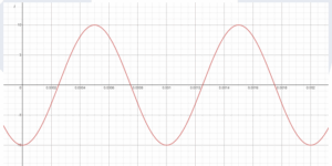
You know that the signal takes the following form:
![]()
Taking measurements from the oscilloscope display, determine 𝐼𝐼𝑝𝑝, 𝑓𝑓 𝑎𝑎𝑎𝑎𝑎𝑎 ∅, and insert those values into the above equation.
Now rearrange your new equation to make the time, t, the subject of this formula and hence accurately determine the first point in time when the current waveform has a magnitude of 6.78 amps.
Get Solution of this Assessment. Hire Experts to solve this assignment for you Before Deadline.
b) The instantaneous value of the electric field vector in a transmitted signal may be described by:
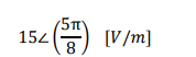
Find the magnitude of the vertical and horizontal components of this field vector.
Note that the symbol ∠ indicates ‘angle’.
Provide a hand-drawn sketch of the electric field vector and its two components, on a set of Cartesian axes.
Task 2:
a) In a circuit under test a resistor, R, is connected in series with a capacitor, C. An a.c. current, 𝑖𝑖, flows through this RC combination, causing a voltage (𝑉𝑉𝑅𝑅) of 6V
Assuming that 𝑉𝑉𝑅𝑅 is in-phase with 𝑖𝑖, and 𝑉𝑉𝐶𝐶 lags 𝑉𝑉𝑅𝑅 by 90𝑜𝑜, draw a vector diagram for this arrangement and then calculate the magnitude of the resultant voltage across the whole RC combination.
b) You are measuring the force, F, on an electrical conductor operating in the magnetron of a microwave oven, which is subject to a strong magnetic field. The current may be modelled in three-dimensional space as:
𝐼 = 3𝑖 − 5𝑗 + 7k
and the magnetic field as:
𝐵 = 2𝑖 + 4𝑗 − 8k
Determine the force, F, as the cross product of the current vector and magnetic field vector, (i.e., find I X B ) Using a 3-dimensional Cartesian axis system, draw all three vectors, or use software to do so.
c) Using the dot product, determine the angle between the current vector and the magnetic field vector.
Task 3:
PART 1
Your company produces radio transmitters and part of that circuit uses a ring modulator to multiply a high frequency sinusoidal carrier signal with a much lower frequency audio signal to transmit over long distances using amplitude modulation, (AM).
The ring modulator circuit works by multiplying together the 125 kHz carrier signal, Vc, and the 10 kHz audio signal, Va, to produce the transmitted modulated signal output, Vo. The two signals and the output from the
ring modulator are described as follows:

Use one of the graphical packages listed at the beginning of this assignment to plot 𝑉𝑐 ,𝑉𝑎,𝑎𝑛𝑑 𝑉𝑜, and include a screenshot of your plot as part of your submission. Ensure the scale of both axes is carefully chosen to clearly show the detail of all 3 waveforms.
If you drew a smooth curve linking the peaks of the positive half cycles of the output waveform, Vo, which is called the envelope of the waveform, what can you observe about that curve?
Stuck in Completing this Assignment and feeling stressed ? Take our Private Writing Services
PART 2
Using the information contained in Section 2.3 of Workbook 2 on Trigonometric Identities, develop an alternative expression for Vo, to show that the output from the multiplier circuit comprises frequency components at 115 kHz, 125 kHz, and 135 kHz.
Subsequently, plot your alternative mathematical expansion to demonstrate that the two versions of the output signal, Vo, from Part 1 and Part 2, are identical.